Инструменты пользователя
Боковая панель
Analog-to-digital conversion
Hello. I am Nikita Kipriyanov, from Voronezh, Russia. I have a masters degree in physics, so I like themes like this one. I would talk about signal domain conversion - from analog to digital.
At present, the analog-to-digital conversion is widely used in the world. It is everywhere: in dial-up, DSL and cable modems; in all modern TVs capable of receiving legacy terrestrival broadcast; in cell phones - not only for voice part but also for microwave part, and so on. This is the only way for computer to percept anything from the reality. With modern powerful digital signal processors it is much easier to convert a signal to digital domain early and then process it in that form, following a generic modular path, rather than develop a special device for each use case, so more and more previously analog-only solutions gone digital.
We're talking about the audio analog-to-digital conversion.
The converison, often called sampling as a whole, is said to be done in two distinct steps.
Sampling
The first step is called discretization, or just sampling. I know, it's confusing, but there is nothing can be done.
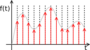
 Sampling is simply measuring the voltage at some known moments. These moments for simplicity are always equidistant, and the frequency of that moments called sampling frequency.
There is a strong analytical theorem, called Nyquist-Shannon theorem (in my country it is called Kotelnikov theorem, because Kotelnikov proved it in 1933, and Shannon proved same Nyquist's statement in 1949). It says: if the finite function has finite spectra with no frequencies higher than f, it can be perfectly and exaclty reconstructed from an infinite sequence of discrete samples (each is of infinite precision), arriving at rate just higher than 2f.
Let our input voltage be the function - it would always be finite - and our task here is to find out these samples. We alredy done an approximation here. The function should be of finite spectra, and such function inevitable will be infinitely long. And our sequence should be infinite too. But all sequences are finite in reality! Let's forget about this approximation.
Low-pass filter
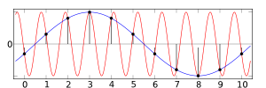
 First thing to do is that we have to band-limit our voltage. Remember, the function shouldn't have too high frequencies? It will have. We should construct an analog filter that rejects everything over half the sampling frequency before we sample it. If we fail to do that, we will get aliasing - some higher-than-half frequencies will reflect around that half-frequency and appear as lower-than-half. Depending on the case, it can (really can, trust me!) drastically reduce quality of sound. We really shouldn't give any higher-than-half frequency any chance to get through!
The picture at left shows us what is going there. The red part is actual signal, and black dots and vertical lines are samples. It is clearly seen that frequency of red sine is more than a half of frequency of black lines. So after reconstruction, we get wrong one - a blue sine! It is unwanted and is there just because we haven't bothered to remove the too-high-frequency red one.
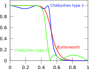
 This is called analog low-pass filter. There is a couple of these filters - Butterworth, Chebyshev, other ones - but no filter can just cut the spectra at some frequency - they all have some transition band, in which the filter response curve smoothly falls to zero. So the low-pass filter that said to be «20 kHz» in fact may allow 21 kHz component to pass, but that component will have a very low energy. The «speed» how fast the filter falls, also called the slope, is meashured in decibelles per octave (dB/oct), and defines our transition band width.
It is not hard to build very sharp filter; it is simply several filters chained together. But, the electronic components need to be precise, and will introduce thermal noise. In general, the less componens there is, the better sound is. Another caveat is that any filter has side-effects. The more slope is, the more would be impact on good parts of the signal.
The common filter response curves at left gives us an idea what impact is going there. Buttworth (red line) is sooo sloooow and diminishes frequencies near cutoff, Chebyshevs either wont remove all unneeded frequencies (green line) or will somewhat hurt needed ones (blue line).
At which frequency?
Since the human hearing range ends near 20 kHz, all filters are built to cut right after that, so to be able to capture on 48 kHz there should be enough filter slope for spectra to end on 24 kHz. This is very sharp. So almost every sound card actually captures in a frequency much more than 48 kHz - actually 256x and more (this is called oversampling), so allowing much wider transition bands and just cheap low-pass filters with less precise components. Then, after all conversions, we can do digital low-pass filtering (with similar Chebyshev or Butterworth or elliptic filter) and then resampling to desired sampling frequency. The digital filter would do much better, since it is cheap and we don't need to carefully select components, also noise here is just rounding error. It still has side-effects, but the control over them is also better. Since oversampling frequency is always multiple of desired frequency, the resampling is just decimation - we take only first sample of, for example, each eight.
Now we ready to sample our signal. Here goes next step. It is called quantization.
Quantization
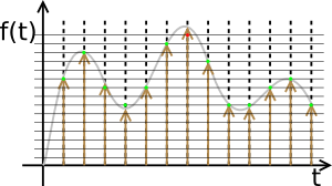
Remember, our samples were of infinite precision? The computer can not handle such things as «infinite precision numbers». It can have arbitrary long number, but it is limited in range and in precision. All of this is expressed in number of bits. Converter rounds each sample to known number of bits, introducing rounding error. This error is known as quantization noise. How many bits to choose? The number of bits limits our signal-to-noise ratio (SNR), a dynamic distance between sound and noise. It is also limits the range of amplitudes we can express, the dynamic range. The voltage over limit can not be expressed, but it needs, and all converter can do is to express it with maximum possible value - to clip. This sounds like ugly distorted trahsing sound, so don't allow any of it! Never go red! If the clipping occurs, just throw record away, lower preamp and re-record.
 Look onto the picture. The samples are quantized - the some points are on same horizontal lines, even thought their arrows are of different lengths. The whole graphic is 4-bit, since there is 16 distinct levels of voltage (horizontal lines), including zero. The sampled signal there is 10, 13, 9, 7, 9, 14, 15, 12, 7, 7, 9, 10, 7. The red one should be 16 will it be there - but no 16 exists in 4-bit world, the numbers are from 0 to 15. So this sample was clipped.
This is the digitized sound (and picture, and movie, and anything) looks like - just a sequence of numbers!
How many bits?
There is the rule of thumb: for integer samples each bit adds 6 dB into both SNR and dynamic range. So, 16 bits gives us 96 dB; 24 bits allows up to 144 dB. The dynamic range of voice is 25 dB; the dynamic range of a violin is 45 dB; the dynamic range of a symphonic orchestra can be up to 170 dB. But, there is a caveat. Even best low-pass filter and quantization device (whatever technology it employs) has thermal noise. With the room temperatures and standard line-level signal there can be of 20-22 bits of precision, or 120 dB of SNR. So 24 bits is just enough (this is good round number, three «bytes»). Oversampling helps again, allowing to improve the precision of each sample, adding a few precious bits.
Done!
Finally, we would have a stream of 24-bit numbers arriving at a frequency of 48000 Hertz. It is 144 kilobytes per second of sound for any channel, so stereo sound of 1 minute length would be 17 megabytes. So go and free up some space on your hard drive for your projects!

